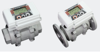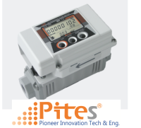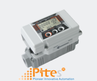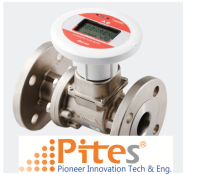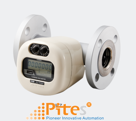
TBX/TBZTURBINE GAS METERS FOR FLOW MANAGEMENT THIẾT BỊ ĐO LƯU LƯỢNG KHÍ DẠNG TURBINE
Nhà cung cấp: pites
Hãng sản xuất: AICHI TOKEI
TBX/TBZTURBINE GAS METERS FOR FLOW MANAGEMENT THIẾT BỊ ĐO LƯU LƯỢNG KHÍ DẠNG TURBINE, Aichi Tokei Denki Vietnam, đại lý Aichi Tokei Denki tại Việt Nam , nhà phân phối Aichi Tokei Denki
TBX/TBZTurbine Gas Meters
for Flow Management
Features
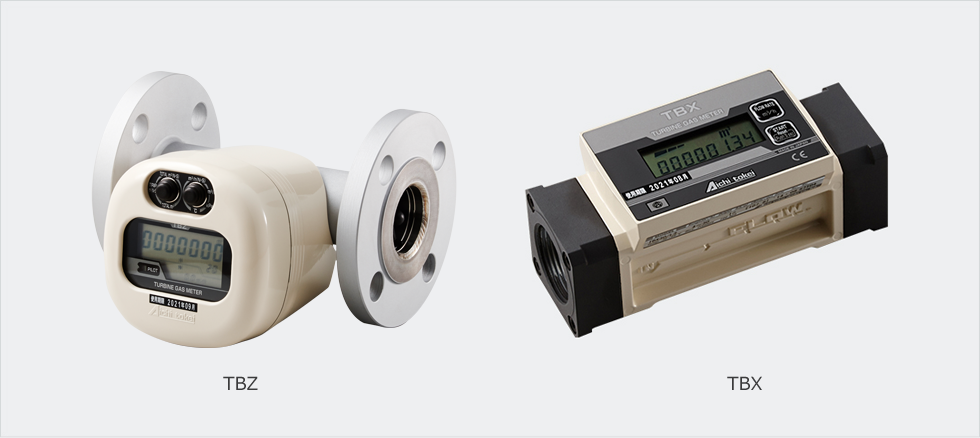
Turbine meters in the TBZ and TBX series were developed for controlling the gas consumption of each piece of equipment such as compact boilers and various industrial furnaces.
The products realize a smart design with a lightweight and compact body and support a wide range of measurement including maximum working pressure and maximum measuring flow rate.
Furthermore, the built-in 2-system pulse transmitters enable you to establish a remote meter reading system and an energy control system.
The TBZ series even corrects temperature and pressure to allow you to read gas consumption in the standard conversion condition.
The external power supply model TBX-D has been newly added to the lineup of the TBX series.
You can choose the model that would best suit your applications for better usability.
Note) TBX30, TBX100, and TBX100F are CE compliant.
(Collaborative development product with Tokyo Gas Co., Ltd.)
・The maximum working pressure covers low, medium and high pressures.
・Free installation positions..

・Equipped with two systems of pulse transmitter.
・Supports a variety of gases and a wider range of applications.
・LCD display that gives you more information.
・Corrects temperature and pressure. (TBZ series).
・Non-stop operation for seven years. (For the battery specifications)
Application examples
・Manage and control gas flows of burning equipment such as burners, boilers and furnaces.
・Manage and control flows of hot and chilled water generators in compact to medium sizes.
・Manage and control flows of gas refrigerators.
・Manage and control gas flows as a part of plant instrumentation.
・For various experimental devices relating to gas flows.
System drawing

Specifications
The model with the correcting function (TBZ series)
| Basic model | TBZ60 | TBZ150 | TBZ300 | |||||||
|---|---|---|---|---|---|---|---|---|---|---|
| Model name | Flow rate correcting model (with the functions of temperature and pressure correction) | - | TBZ 60-3.5 |
TBZ 60-9.9 |
- | TBZ 150-3.5 |
TBZ 150-9.9 |
- | TBZ 300-3.5 |
TBZ 300-9.9 |
| Actual flow rate model (without the functions of temperature and pressure) | TBZ 60-0 |
- | - | TBZ 150-0 |
- | - | TBZ 300-0 |
- | - | |
| Operating flow rate range *1 | 6~60m3/h | 12.5~150m3/h | 30~300m3/h | |||||||
| Maximum operating pressure | 980kPa | 350kPa | 980kPa | 980kPa | 350kPa | 980kPa | 980kPa | 350kPa | 980kPa | |
| Accuracy | Flow rate measuring parts | ±1%FS and ±3%RS | ||||||||
| Operator parts and temperature and pressure correction parts | - | ±2% RSmax |
±3% RSmax |
- | ±2% RSmax |
±3% RSmax |
- | ±2% RSmax |
±3% RSmax |
|
| Display | Corrected gross accumulated flow rate (Only for the corrected flow rate model) |
Large LCD in 9 digits with minimum reading of 10 L | Large LCD in 9 digits with minimum reading of 100 L | |||||||
| Trip flow rate *2 | Large LCD in 8 digits with minimum reading of 10 L | Large LCD in 8 digits with minimum reading of 100 L | ||||||||
| Unadjusted gross accumulated flow rate *3 | Large LCD in 9 digits with minimum reading of 10 L | Large LCD in 9 digits with minimum reading of 100 L | ||||||||
| Corrected instantaneous flow rate (Only for the flow rate correction model) |
LCD in 4 digits with minimum reading of 0.1 m3/h | LCD in 4 digits with minimum reading of 1 m3/h | ||||||||
| Unadjusted instantaneous flow rate | LCD in 4 digits with minimum reading of 0.1 m3/h | LCD in 4 digits with minimum reading of 1 m3/h | ||||||||
| Temperature (Only for the models with temperature and pressure correction) |
LCD in 3 digits with minimum reading of 0.1 m3/h | |||||||||
| Pressure (Only for the corrected flow rate model) |
LCD in 3 digits with minimum reading of 0.1 m3/h | |||||||||
| Diameters of connected parts | JIS 10K 40A flange | JIS 10K 50A flange | JIS 10K 80A flange | |||||||
| Operating temperature range | -10℃~+60℃ | |||||||||
| Measurable gases *4 | Town gas, LPG, nitrogen, etc. | |||||||||
| Mounting position | Horizontal and Vertical (Display supports both directions.) | |||||||||
| Installation location | Indoor and outdoor * 5 | |||||||||
| Case structure | Drip-proof structure, IPX 2 equivalent (JIS-CO920) | |||||||||
| Power source | Built-in lithium battery | |||||||||
| Output signal | Two systems of open collectors (corrected pulse and unadjusted pulse * 6) | |||||||||
| Standard pulse unit width * 7 | 100 L/P Maximum load: 24 VDC and 20 mA; Pulse width: 40 msec |
|||||||||
| Materials | Main piping: Stainless steel; Flange: Steel; Display: Aluminum alloy | |||||||||
| Temperature sensor | Platinum resistance temperature detector thermal sensor: JIS A class | |||||||||
| Pressure sensor | Semiconductor type pressure sensor (High precision) | |||||||||
| Mass | 5.3kg | 6.0kg | 9.4kg | |||||||
*1. Operating flow rate range is the range of the actual flow (unadjusted flow rate)..
*2. Corrected trip accumulated flow rate for the flow rate correction model (with temperature and pressure correction) and unadjusted trip accumulated flow rate for the actual flow rate model (without temperature and pressure correction)..
*3. Under the conditions of pressure 100 kPa or higher for the -3.5 model and 350 kPa or higher for the – 9.9 model where the temperature is at 25°C..
*4. Prevent oil mist (Carbide grade C5 or higher), dust particles and the like from entering into the meter..
*5. Avoid direct contact of water onto the meter if the meter is installed outdoors..
*6: Unadjusted pulse and high-density pulse are the actual pulse synchronized with the rotation of impellers..
*7. TBZ uses corrected pulse while TBX uses unit pulse.
Specifications of actual flow display model (TBX series)
| Model type | TBX30 | TBX100 | TBX100F | TBX150F | |
|---|---|---|---|---|---|
| Operating flow rate range *1 | 4~30m3/h | 10~100m3/h | 10~100m3/h | 12.5~150m3/h | |
| Maximum operating pressure | 100kPa | ||||
| Accuracy | Flow rate measuring parts | ±1%FS | |||
| Display | Trip flow rate *2 | Large LCD in 6 digits with minimum reading of 10 L | LCD in 6 digits with minimum reading of 100 L | ||
| Unadjusted gross accumulated flow rate *3 | Large LCD in 8 digits with minimum reading of 10 L | LCD in 8 digits with minimum reading of 100 L | |||
| Unadjusted instantaneous flow rate | LCD in 3 digits with minimum reading of 0.1m3/h | LCD in 4 digits with minimum reading of 0.1m3/h | LCD in 3 digits with minimum reading of 1m3/h | ||
| Diameters of connected parts | Rc1 1/2、Rc1 1/4 | Rc2 | JIS 10K 50A flange | ||
| Operating temperature range | -10℃~+60℃ | ||||
| Measurable gases *4 | Town gas, LPG, nitrogen, etc. | ||||
| Mounting position | Horizontal and vertical | ||||
| Installation location | Indoor | ||||
| Power source | Built-in lithium battery or external power supply (24 VDC) | ||||
| Output signal | Two systems of open-drain output (unit pulse and high-density pulse * 5) | ||||
| Standard pulse unit width * 6 | TBX30 and TBX100: 10 L/P; TBX150: 100 L/P Maximum load: 24 VDC and 20 mA; Pulse width: 40 msec |
||||
| Materials | Aluminum alloy | Cast iron | Aluminum alloy | ||
| Mass | 0.8kg | 1.8kg | 7.0kg | 2.5kg | |
*1. Operating flow rate range is the range of the actual flow (unadjusted flow rate)..
*2. Corrected trip accumulated flow rate for the flow rate correction model (with temperature and pressure correction) and unadjusted trip accumulated flow rate.
for the actual flow rate model (without temperature and pressure correction)..
*3. In the conditions of pressure 100 kPa or higher for the -3.5 model and 350 kPa or higher for the – 9.9 model where the temperature is at 25°C.
*4. Prevent oil mist (Carbide grade C5 or higher), dust particles and the like from entering into the meter..
*5: Unadjusted pulse and high-density pulse are the actual pulse synchronized with the rotation of impellers..
*6. TBZ uses a corrected pulse while TBX uses a unit pulse.
Dimensions
Dimensions of the turbine meter TBZ

(Unit: mm)
| Model | L | H | W | JIS 10K flange | |||
|---|---|---|---|---|---|---|---|
| φD | φd | aφb | Diameters | ||||
| TBZ60 | 200 | 150 | 197 | 140 | 105 | 4-19 | 40A |
| TBZ150 | 220 | 158 | 211 | 155 | 120 | 4-19 | 50A |
| TBZ300 | 250 | 185 | 246 | 185 | 150 | 8-19 | 80A |
Dimensions of the turbine meter TBX

For TBX100F, the indicator can be moved freely, wherein the meter can accommodate the direction of the gas flow. The indicator can also be removed to be used as a remote display.
(Unit: mm)
| Model | L | H | W |
|---|---|---|---|
| TBX30 | 170 | 74 | 73 |
| TBX100 | 200 | 100 | 85 |
| TBX100F | 200 | 161 | φ155 |
| TBX150F | 200 | 148 | φ155 |
Strainer (sold separately)
Make sure to install the strainer in the upstream side of the flow meter in order to maintain the performance of the flow meter as long as possible.
* Consideration of pressure loss will be necessary.
Standard specifications
| Model | YKDS32 | YKDS40 | YKDS50 | YF50 | YDF40 | YDF50 | YDF80 |
|---|---|---|---|---|---|---|---|
| Maximum operating pressure (kPa) | 500 | 500 | 500 | 500 | 980 | 980 | 980 |
| Body material | FCD450 | FCD450 | FCD450 | FCD200 | FCD-S | FCD-S | FCD-S |
| Diameter (A) | 32 | 40 | 50 | 50 | 40 | 50 | 80 |
| Connection | Rc1・1/4 | Rc1・1/2 | Rc2 | JIS10K(FF) | JIS10K(RF) | ||
| Mass (kg) | 2.3 | 2.9 | 4.5 | 8.2 | 8.5 | 11 | 15 |
| Supported models | TBX30(32A) | TBX30(40A) | TBX100 | TBX100F・150F | TBZ60 | TBZ150 | TBZ300 |
Dimensions: Screw type
(Unit: mm)
| Model | A | L | H (in approximate) |
|---|---|---|---|
| YKDS32 | 32 | 145 | 105 |
| YKDS40 | 40 | 160 | 110 |
| YKDS50 | 50 | 180 | 130 |

Dimensions: Flange type
(Unit: mm)
| Model | A | L | H (in approximate) |
|---|---|---|---|
| YF50 | 50 | 220 | 130 |
| YDF40 | 40 | 240 | 155 |
| YDF50 | 50 | 250 | 170 |
| YDF80 | 80 | 320 | 215 |

・Specifications are subject to change without notice.
・Product Warranties


 Mr. Hà
 live:ha_1652