MBC Dungs Vietnam , MBC COMBUSTION CONTROLS Vietnam
Nhà cung cấp: Pitesco
Hãng sản xuất: DUNGS , DUNGS COMBUSTION CONTROLS
 Mr. Hà
 live:ha_1652
DUNGS , DUNGS Vietnam , DUNGS Viet nam , DUNGS COMBUSTION CONTROLS , DUNGS COMBUSTION CONTROLS Vietnam
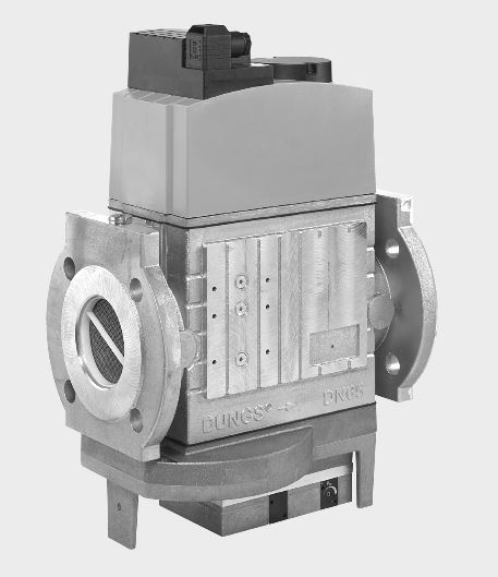
Technical Description
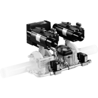
The DUNGS multiple actuator MBC-...-SE integrates valves and servo pressure regulator in one compact unit:
- Solenoid valves up to 500 mbar (50 kPa) as per DIN EN 161 Class A Group 2
- Fine setting of outlet pressure
- Servo pressure regulator unit as per DIN
EN 88 Class A Group 2
- Setpoint spring replaced
-Outlet pressure: 4 - 300 mbar (0.4 - 30 kPa)
-Internal stepping lines for optimised outlet pressure stability, external as an option.
- Flange connection as per EN 1097-1
- Easy to install
- Low weight
As this system has a modular design, we can offer individual solutions with valve testing system, mini/maxi pressure switch
and pressure limiter. Despite the compact design, high flow rates can be achieved at low pressure difference. Application
The servo pressure regulator permits optimal mixture formation in forced air burners and premix burners in combination with mechanical or electronic gas/air regulation units. This applies to modulating and multistage variable operating modes.
Suitable for gases belonging to gas families
1, 2, 3 and other inert gaseous media.
Approvals
EC type testing certificate as per:
•
EC-Gas Appliances Regulation
•
EC-Pressure Equipment Directive
Approvals in other important gas-consuming countries.
Printed in Germany • Edition 01.18 • Nr. 231 888
2 ... 8
Functional Description
Gas flow
1. If the valves V1 and V2 are closed,
chamber a is subjected to inlet pres
-sure up to the double seat of the valve V1.
2. The min. pressure switch (option) is connected to chamber a via a bore hole. If the inlet pressure exceeds the desired value set on the pressure switch, the pressure switch connects through to the gas burner control system.
3. The valves V1 and V2 open after they
are enabled by the gas burner control
system. Gas flow through chambers
a, b and c is enabled.
Functional description of the combined
valve-regulator unit at valve V1
A regulator (pressure regulator unit)
with admission pressure compensation
is integrated in valve V1. The plunger
V1 is not connected to the valve disc
unit. When the plunger opens, it
preloads the compression spring and
releases the regulator unit. When the
plunger closes, the closing pressure
is applied directly to the valve discs of
the regulator unit. Valves V1 and V2 are
driven together electrically. When valve
V3 is in the closed position, it closes off
the pressure chamber under the work
-
ing diaphragm M so that this chamber
is not affected by the inlet pressure p1
in chamber a. The plunger of valve V1 controls the valve V3. The pressure under the working diaphragm M depends on a variable flow cross-section D. The outlet pressure p Br
counters the force
of the setting spring E via the servo
diaphragm S until an equilibrium of
forces is achieved.
Ambient pressure p
amb
is applied to the
opposite side of the servo diaphragm.
If there are any changes in the equilib
-
rium of forces, the flow cross-section
D after the valve V4 is changed. The
pressure under the working diaphragm
is re-adjusted. The regulator unit V1
adapts the free valve cross-section to
the new flow requirement.
Functional description valve V2
The plunger of the valve V2 is connected
to the valve disc unit. When the plunger
opens, it preloads the compression
spring. The valve V2 opens completely
without any delay. The valve V4 is actuated by the valve V2. When the valve
V4 is in the closed position, it closes off the area under the working diaphragm M so that this area is not affected by the
burner pressure.
Schematic diagram MBC-...-SE
Pressure taps, gas train diagram
MBC-...-SE
a, b, c
Pressure chambers
in flow direction
p
1
Inlet pressure
p
Br
Burner pressure, outlet pressure
p
amb
Ambient pressure
2, 3, 4, 5
Screw plug G 1/8
1, 6
Screw plug G 1/4
7
Stepping line
p
Br
V1
Main valve 1
V2
Main valve 2
V3
Control valve 3
V4
Control valve 4
M
Working diaphragm
D
Restrictor
S
Servo diaphragm
E
Setting spring for
outlet pressure p
Br
Closing function
If there is an interruption in the power
supply to the solenoid coils of the main
valves V1 and V2, they are closed by
the compression springs in <1s.
7
11
12
9
5
4
1
2
3
8
2
2
3
3
4
4
7
5
5
11
10
12
6
9
9
1
1
8
8
6
p
Br
p
amb
V3
V4
c
b
a
D
M
S
E
p
1
V2
V1
V1
V2
V3
V4
p
2
p
1
3 ... 8
Technical Data
Nominal widths Max. operating overpressure Inlet pressure ranges Burner pressure ranges Media
Ambient temperature
Dirt trap device
Pressure switch
Servo pressure regulator
Solenoid valve V1, V2
Measuring gas connection
Stepping line
Voltage / frequency
Electrical connection
Power / current draw
Switch-on duration
Degree of protection
Material used for gas-conveying parts
Installation position
Power / current draw
at ~(AC) 230 V, + 20 °C
all indications are effective values
DN 65 80 100
Connection flanges as per EN 1092-1 for welding neck flanges as per
DIN 2633 (PN16) DN 65 - DN 100
Length as per DIN 3202 part 1, series F1.
500 mbar (50 kPa)
p
e
= 15 - 500 mbar (1.5 - 50 kPa)
Standard:
p
Br
: 20 - 40 mbar (2 - 4 kPa)
Option:
See spring table, page 4
Gases belonging to gas families 1, 2, 3 and other inert gaseous media.
-15 °C to +60 °C
Filter
A suitable gas filter must be connected upstream.
For further information, see data sheet 11.02 “Gas and air filter”.
The system can be equipped with pressure switch types GW A5, ÜB A2, NB A2 as per DIN
EN 1854. In case of DN 65 GW...A5 cannot be mounted on item 2. For further information,
see data sheets 5.07 and 5.02 “Pressure switches for DUNGS multiple actuators”.
Pressure regulator with admission pressure compensation, sealed with valve
V1 when switched off, as per DIN EN 88 Class A
Servo pressure regulator with adjustable burner pressure
Valve as per DIN EN 161 Class A Group 2; fast-closing, fast-opening S..0: driven
together; S..2: driven separately
G 1/4 DIN ISO 228; at inlet and outlet flanges, G 1/8 on both sides after the filter,
on both sides between V1 and V2, after V2 (if the pressure switch is assembled, it
may not be possible to install a measuring gas connection in some cases)
G 1/8 connection as per DIN ISO 228 for burner pressure (pBr; gas)
Stepping line for optional, external pulse must be made of steel and
conform to PN1, DN4. The condensate from the stepping line may not
enter the fitting. The operating and assembly instructions must be strictly
followed.
~ (AC) 50 - 60 Hz 230 V -15 % +10 %
Standard voltages: 110 - 120 VAC, 24 - 28 VDC
Plug-in connection as per DIN EN 175301-803
at ~ (AC) 230 V; +20 °C: see type overview
100 % ED
IP 54 as per IEC 529 (EN 60529)