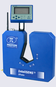
CS3G-C Series _Proton Vietnam, Thiết bị đo đường kính cáp, Proton PTC Vietnam
Xuất sứ: UK
Hãng sản xuất: Proton
EXTRUSION CONTROL
NEXiS® CS3G-C Series Extrusion Controller
Mid-range insulation diameter control with colour LCD touch-screen display.
- For control of one extruder or capstan drive from one or two diameter gauges.
- Integrates with Proton Products DG or DG-k Series Diameter Gauges for insulation diameter measurement.
- Colour 800×480 LCD touch-screen display.
- Auto-compensation control algorithm adjusts P-term as a function of insulation cross-sectional area.
- Statistical analysis and Statistical Process Control (SPC) for minimizing material consumption.
- Panel mounted; optional stand-alone enclosure is available.
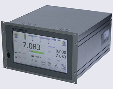
NEXiS® CS3G-C Series - front view
Introduction
The Proton Products NEXiS® CS3G-C Series of controllers are for use on wire insulation or other extrusion production lines.
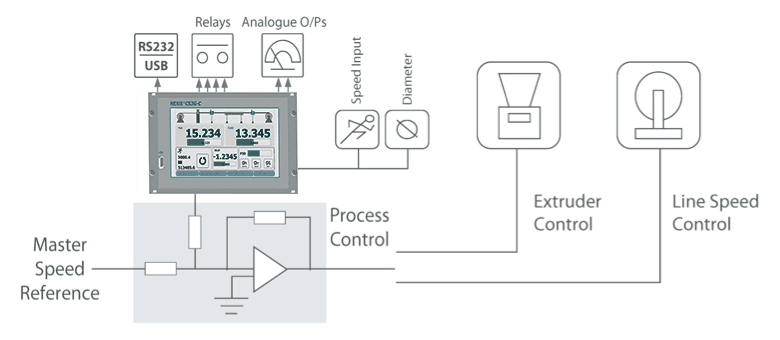
NEXiS® CS3G-C Series controllers connect to Proton Products diameter gauges and speed and length gauges for measurement of insulation diameter and line speed respectively. These measurements are then fed into a PI feedback controller whose fully-isolated and floating output may be used to drive insulation extruders or capstan drives.
Insulation diameter is thus actively controlled and kept in tolerance by the NEXiS® CS3G-C controller.
NEXiS® CS3G-C Series controllers also have advanced features such as a large, high-resolution colour LCD screen with resistive touch panel, password protection, product recipe presets, and Single Scan Flaw Detection (SSFD, for detection of insulation lump and neck flaws).
Variants
|
Variants
|
Control algorithm
|
|---|---|
| NEXiS® CS3G-C-D | Diameter control |
| NEXiS® CS3G-C-HC | Hot-Cold automatic shrinkage compensation control |
INSULATION DIAMETER CONTROL
Cold diameter only (single DG / DG-k gauge – CS3G-C-D variant)

The NEXiS® CS3G-C is connected to the Cold DG / DG-k diameter gauge after the water cooling trough. The Cold diameter measurement is used to control the extruder so that the final insulation diameter is held within tolerance. Since the Cold diameter measurement is located far from the extruder, this control system response time is relatively slow (and dependent on the line speed), but the controlled diameter is the final product diameter.
Hot diameter only (single DG / DG-k gauge – CS3G-C-D variant)

The NEXiS® CS3G-C is connected to the Hot DG / DG-k diameter gauge before the water cooling trough. A shrinkage offset due to cooling is set by the operator and used in conjunction with the Hot diameter measurement to control the extruder so that the final insulation diameter is held within tolerance. Since the Hot diameter measurement is located close to the extruder, this control system response time is relatively fast.
Hot and Cold diameters (two DG / DG-k gauges – CS3G-C-HC variant)

The NEXiS® CS3G-C is connected to the Hot and Cold DG / DG-k diameter gauges before and after the water cooling trough respectively. The shrinkage offset due to cooling is automatically calculated from the Hot and Cold diameter measurements and used in conjunction with the Hot diameter to control the extruder so that the final insulation diameter is held within tolerance. Since the Hot diameter measurement is located close to the extruder, this control system response time is relatively fast and the user does not need to estimate a shrinkage offset.
Specifications
| Screen | Back-lit colour 800×480 LCD display with resistive touch panel | |||||
| Serial communications | RS232 | USB | CANbus - (for connection to up to 2× DG Series gauges) | |||
| Line speed inputs | Analogue | Two inputs available for 0 to 10V and 0 to 50V analogue line speed signals; end-user configurable scaling | ||||
| Pulse | Two inputs available for 0 to 3V and 0 to 10V pulsed line speed signals; maximum frequency 250 kHz; end-user configurable scaling | |||||
| 4×Relay contact outputs | Function (end-user configurable) | Gauge OK | SSFD lump or neck flaw detected | X or Y upper tolerance exceeded | X or Y lower tolerance exceeded | |
| X upper tolerance exceeded | X lower tolerance exceeded | Y upper tolerance exceeded | Y lower tolerance exceeded | |||
| Electrical | Maximum voltage | 50VDC / 30VAC | ||||
| Maximum current | 500mA | |||||
| On resistance (@ 100mA) | < 0.1Ω | |||||
| Off resistance | > 10 MΩ | |||||
| Analogue output 1 | Function (end-user configurable) | ØX | ØXY | |||
| Electrical | Output voltage range | 0V to +10V | ||||
| Maximum output current | 2mA | |||||
| Resolution | 16-bit | |||||
| Output voltage scaling is end-user configurable | ||||||
| Analogue output 2 | Function (end-user configurable) | ØY | Average Error | |||
| Electrical | Output voltage range | ØY: 0V to +10V | ||||
| Average Error: -10V to +10V | ||||||
| Maximum output current | 2mA | |||||
| Resolution | 16-bit | |||||
| Output voltage scaling is end-user configurable | ||||||
| Control algorithm | Advanced Control Algorithm (ACA) | |||||
| SPC | Graphical histogram | Cp | Cpk | |||
| SPC control | Statistical Process Control: minimize insulation material consumption whilst maintaining in tolerance insulation diameter | |||||
| FFT | Fast Fourier Transform: displays amplitude versus frequency of periodic diameter variations | |||||
| SSFD | Single Scan Flaw Detection: detection of lump and neck flaws | |||||
| Presets | Nominal diameter | +Tolerance | -Tolerance | +Flaw (Lump) | -Flaw (Neck) | |
| Product recipes | 50 sets of product presets may be stored in memory for rapid recall | |||||
| Statistics | Mean diameter | Standard deviation (sigma) | Maximum diameter | Minimum diameter | ||
|
Specification
|
Minimum
|
Typical
|
Maximum
|
Units
|
|---|---|---|---|---|
| Weight | 2.5 | kg | ||
| 5.5 | lb | |||
| Length | 231 | mm | ||
| 9.1 | inch | |||
| Width | 213.1 | mm | ||
| 8.4 | inch | |||
| Height | 128.5 | mm | ||
| 5.1 | inch | |||
| Power supply voltage (rms) | 85 | 264 | VAC | |
| Power supply frequency | 47 | 65 | Hz | |
| Power supply current (rms) | 2.5 | A | ||
| Power consumption | 110 | W | ||
| Ambient temperature | 5 | 45 | °C | |
| 41 | 113 | °F | ||
| Relative humidity @ 38°C / 105°F | 90 | % | ||
| Ingress Protection (IP) rating | IP50 | - | ||
| PI Controller output voltage | -10 | 10 | V | |
| PI Controller output current | 10 | mA | ||
| PI Controller output resistance | 10 | Ω | ||
| PI Controller resolution | 12 | bit |


 Ms. Trinh
 trinh trinh
