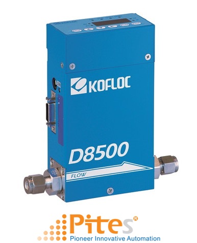
MASS FLOW METER WITH INDICATOR MODEL D8500 kofloc Vietnam
Hãng sản xuất: KOFLOC
 Mr. Hà
 live:ha_1652
MASS FLOW METER WITH INDICATOR MODEL D8500 kofloc Vietnam, MASS FLOW METER WITH INDICATOR MODEL D8500 kofloc Viet nam. MASS FLOW METER WITH INDICATOR MODEL D8500 kofloc
KOFLOC Vietnam, KOFLOC Viet nam, KOFLOC
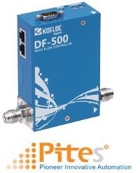
This mass flow controller/meter driven by a 24 VDC power supply has been developed as a successor to the MODEL8300.
The view point change function of the display unit and the pattern setting function are unique to this model, and noise resistance has been improved dramatically. A sister model with a detachable display and setting unit is also available.
Features
・The high-lift actuator allows this compact model to control a large flow rate.
・Equipped with a display and setting unit, this model can be op-erated by a 24 VDC power supply.
・ The RS232C/RS485 communication function and integration function are provided as standard equipment.
・ The 14-bit converter permits display and operation in 4-1/2 dig-its.
・ Control of the flow rate of inflammable gas is possible, because the heat generating part of the sensor is not exposed to gas.
・ There are no limitations on the mounting position that may be employed.
・ In addition to SV setting, five other patterns can be set.
・ Auto zero and auto close functions are also standard.
Standard Specifications
| Flow range (F.S.) (at N2 calibration conditions) | 50 SCCM–5 SLM | Over 5 SLM–20 SLM | |
| Applicable gases (dry gas) | N2, air, O2, CO2, Ar, H2, He, etc. | ||
| Sensor | Thermal mass flow sensor | ||
| Valve actuator | Normally-closed solenoid valve actuator *7 | ||
| Valve type | Poppet valve *7 | ||
| Control system |
Control/measurement range | 2–100% F.S. | |
| Response | 0–100% F.S. or more within 2 sec. *1 0–below 10% F.S. within 4 sec. *1 |
||
| Accuracy | Flow accuracy | ±1.0%F.S. *2 | ±1.5%F.S. *2 |
| Repeatability | ±0.75%F.S. | ||
| Pressure | Proof pressure | 1000 kPa (G) | |
| Allowable operating pressure | 500 kPa (G) or less | ||
| Operating differential pressure *7 | 50–300 kPa (G) | 100–300 kPa (G) | |
| Temperature | Allowable operating temperature | 5–45℃ | |
| Temperature characteristics | 0.2% F.S./℃ | ||
| Humidity | Allowable operating humidity | 10–90% (No condensation allowed) | |
| Leak | He leak rate | 1 × 10⁻⁸ Pa·m3/sec. or less *3 | |
| Flow setting method |
Digital | (1) Setting & display unit | |
| (2) Communications | |||
| (3) Event input selection | |||
| Analog *7 | (1) 0–5 V (2) 4–20 mA (freely selectable) | ||
| Flow rate output | Analog | (1) 0–5 V (2) 4–20 mA (interlocked with the above) | |
| Display | Display format | 7-segment 4-digit LED | |
| Total flow | 12 digits *4 | ||
| Mounting direction | Changeable | ||
| Built-in/Separate | Built-in, separate 1 m, separate 3 m, separate 5 m | ||
| Status display LED | OK (within allowable range), ALM (alarm output interlock) OUT1 (event output 1 interlock), OUT2 (event output 2 interlock) SV (set flow), PV (instantaneous flow), TF (total flow) IF (mode setting) |
||
| Other I/O functions |
Event input | 3 × contact input | |
| Alarm output | 1 × open collector output, Max. 35 V, 50 mA | ||
| Event output | 2 × open collector output Max. 35 V, 50 mA | ||
| Communications | RS-485, half-duplex, 9600 bps | ||
| Power supply | Rating | 24 VDC, current consumption: 300 mA max. | |
| Allowable supply voltage range | 21.6–26.4 VDC (Ripple: 5% or less) | ||
| Mounting position | Not specified | ||
| Applicable standards | RoHS and EN62326-1: 2006 | ||
| Materials of parts in contact with gases |
SUS316, SUS316L, SUS430, FKM, PTFE, chloroprene rubber (option) |
||
| Joint | 1/4 SWL, RC1/4, 1/4 VCR | ||
| Weight | Built-in: Approx. 1000 g Separate (excluding the cable): Approx. 1200 g (*6) |
||
| (*1) Time required to reach the control flow ±2% F.S. from the fully closed state | |||
| (*2) With the standard pressure of 200 kPa (G) and the standard temperature of 20℃ | |||
| (*3) Permeation is not included. The leakage by prolonged permeation shall not exceed 1 × 10⁻⁶ Pa・m3/sec. | |||
| (*4) The units of measurement vary with the full scale flow. E.g.: With 1 SLM, the flows can be added up to 9999 9999 9.999 L. | |||
| (*5) For other joints, please contact us. (*6) The weight may slightly vary depending on the joint. (*7) These apply to the D8500MC mass flow controller. | |||