wika-vietnam-dong-ho-ap-suat-wika-model-230-15-332-54-432-50-433-50-611-10-631-10-632-50-633-50-110-10r-111-1rf-111-16-111-26-111-31-112-28-132-28-111-10dw-111-12dw-232-30-233-30.png

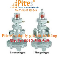
Models 432.50, 433.50

Diaphragm pressure gauge

Process Industry Series Sealgauge Dry Case / Liquid-filled Case

Applications for diaphragm pressure gauges:

  • With liquid filled case for applications with high dynamic pressure pulsations or vibration
  • Suitable in corrosive environments for gaseous, liquid or highly viscous media.
  • Process industry: chemical/petrochemical, power stations, mining, on and offshore, environmental technology, mechanical engineering and plant construction

Special features of diaphragm pressure gauges:

  • Threaded or open flange process connections
  • Wide selection of special materials
  • All stainless steel construction
  • High overpressure safety
  • Ranges from 6" H20 (16 mbar)

Specifications for diaphragm pressure gauges:

Diaphragm pressure gauges measure gauge, absolute and differential pressure. In processing industries, they can be installed in applications with highly corrosive, viscous media.

Diaphragm pressure gauges are ideal for these harsh conditions because the media can clog the narrow presure ports of threaded connections of Bourdon tube instruments as well as the internals of the tube.

To prevent such clogging, diaphragm pressure gaugesare connected to the process with an open flange. This configuration provides a large pressure chamber, which prohibts media from settling.  

Design
EN 837-3

Sizes
4” & 6” (100 & 160 mm)

Accuracy class
± 2.5% of span

Ranges
Vacuum / Compound to 300 psi (20 bar)
Pressure from 6” H2O (16 mbar) to 100" H2O (250 mbar), 6" (160 mm) flange diameter
Pressure from 6 psi (400 mbar) to 360 psi (25 bar), 
4” (100 mm) flange diameter
or other equivalent units of pressure or vacuum

Working pressure
Steady: full-scale value
Fluctuating: 0.9 x full-scale value

Overpressure safety
5 x full-scale value, not exceeding 600 psi (40 bar)

Operating temperature
Ambient: -4°F to +140°F (-20oC to +60oC)
Medium: +212°F (+100oC) maximum
Storage: -40o to +158°F (-40oF to +70oC)
               -4oF to + 158oF (-20oC to +70oC) for  
               ranges ≤25 H2O (60mbar)

Temperature error

Additional error when temperature changes from reference temperature of 68°F (20°C) ±0.8% of span for every 18°F (10°K) rising or falling.


Diaphragm pressure gauges, also called sealgauges, are suitable for low pressure and overpressure conditions. 

WIKA's standard design diaphragm pressure gauges (in stainless steel or Inconel) meet NACE 0175 standards, up to 120° C and are suitable for sour gas applications.  


Weather protection

Weather resistant (NEMA 3 / IP54) - dry case
Weather tight (NEMA 4X / IP66) - liquid-filled case

Case and upper diaphragm housing
Material: stainless steel
Case with pressure relief disc and stainless steel bayonet ring

Pressure connection and lower diaphragm housing
Material: 316L SS
Lower mount (LM)
½” NPT female

Diaphragm element
≤ 100” H2O (250 mbar): 316 SS with PTFE lining
> 100” H2O (250 mbar): Inconel® (NiCr-alloy) with PTFE lining
All ranges with FPM (Viton) sealing gasket

Movement
Material: stainless steel

Dial
White aluminum with black lettering

Pointer
Black aluminum, adjustable - Type 432.50
Black aluminum, non-adjustable - Type 433.50

Window
Laminated safety glass with Buna-N gasket

Case fill
Standard dry
Glycerine 86.5% - Type 433.50

Models 611.10, 631.10

Low Pressure Capsule Gauges

611.10, Copper Alloy Wetted Parts 631.10, Stainless Steel Wetted Parts

Description

Design
EN 837-3

Nominal Sizes
2", 2½" (63 mm)

Accuracy
+ 1.6% of FSV

Standard Ranges
2":    0...25 INWC (60 mbar) to 0...250 INWC (600 mbar)
2½":    0...10 INWC (25 mbar) to 0...250 INWC (600 mbar)
or all other equivalent vacuum or compound ranges

Standard Scales
In.H20/mmH20
oz/sq.in/mmH20
oz/sq.in/In.H20
PSI

Pressure limitation
Steady: Full scale value
Fluctuating: 0.9 x full scale value

Permissible temperature
Ambient:-4°F...+140°F (-20...+60°C)
Medium. + 212°F (+100°C) maximum

Temperature Error
Additional error when temperature changes from reference temperature of 68°F (20°C) +0.6% of span for every 18°F (10°K) rising or falling.

Ingress protection
NEMA2 (IP 32 per EN 60529 / lEC 529)

Process connection
Model 611.10: Copper alloy
Model 631.10: Stainless steel
Lower mount (LM) or back mount (CBM)
(2": Only back mount)
¼" NPT (male), 14 mm flats


Pressure element
Model 611.10: Copper alloy
Model 631.10: Stainless steel

Sealing
NBR

Movement
Copper alloy

Zero adjustment
At the front

Dial
Aluminium, white, black lettering

Pointer
Aluminium, black

Case
Steel, black

Window
Clear plastic

Model 212.20

Bourdon Tube Pressure Gauges

Industrial Series Gauge

Specifications

Design
ASME B40.100 & EN 837-1

Sizes
4", 6” (100 mm, 160 mm)

Accuracy class
± 1% of span (ASME B40.100 Grade 1A)

Ranges
Vacuum / Compound to 200 psi (16 bar)
Pressure from 15 psi (1 bar) to 15,000 psi (1,000 bar)
or other equivalent units of pressure or vacuum

Working pressure
Steady: full scale value
Fluctuating: 0.9 x full scale value
Short time: 1.3 x full scale value

Operating temperature
Ambient: -40°F to +140°F (-40°C to +60°C)
Medium: +140°F (+60°C) maximum

Temperature error
Additional error when temperature changes from reference
temperature of 68°F (20°C) ±0.4% of span for every 18°F (10°K) rising or falling.

Weather protection
Weather resistant (NEMA 3 / IP 54)

Pressure connection
Material: copper alloy
Lower mount (LM) or lower back mount (LBM)
1/2” NPT

Bourdon tube
≤ 1,000 psi (70 bar): C-shape copper alloy
> 1,000 psi (70 bar): Helical 316 stainless steel

Movement
Brass

Dial
White aluminum with black lettering

Pointer
Black aluminum

Case
304 stainless steel with stainless steel bayonet ring

Window
Flat instrument glass